MRID
Brand:PTT
Video Reference
Dual Lasers Auto switch Micro Raman Spectrometer
Polarized Micro Raman system --- ProTrusTech MRID
Raman Polarization Rotating Mapping (RPRM)---PTT Auto Raman Spectroscopy
Auto scan polarization micro raman spectroscopy
MRID (Micro Raman Identify Dual Lasers)
The MRID (Micro Raman Identify Dual Lasers) system is protected by patents in Taiwan (I709732) and the United States (US 11,340,114 B2). This patented design is based on an optical setup with built-in direct light path, dual-laser sources and dual spectrometers. Software controls the switching between different laser wavelength to achieve fully automatic microscopic Raman laser source selection, requiring no manual adjustments. Combined with the highly stable optical system, which eliminates the need for an optical table, the overall design significantly reduces operational complexity, allowing even users without any background to operate the system easily.
The MRID features a horizontally interleaved optical light path and can be customized with a third or additional laser sources via fiber input according to customer requirements, making it convenient for users to switch lasers or adapt the system for other applications.
-
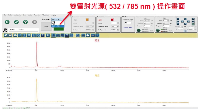
Dual- Laser Measurement
Independently developed by Protrustech and protected by a patent, the dual-laser system allows users to measure Raman signals from different laser wavelengths with a single button click. As shown in the figure, a silicon wafer under a 785 nm laser get a peak at 520 cm-1 and shows thermal effects in the NIR range. Another Raman spectrum illustrates the typical response of a silicon wafer under a 532 nm laser. This design can also be customized to:
-
Two type of laser power controlling interface
Two software-controlled methods are available for laser power adjustment. A continuous neutral density filters (O.D. 2.0~0.04) with a built-in laser power calibration curve allows precise control with accuracy of better than 1%. Both default and user-defined laser power transmittance (%) are supported. Additionally, laser output power can be adjusted via software in 1 mW steps.
By combining these two control functions, the laser power can be finely tuned to a minimum output of 0.01 mW 1%.

ND control : User-input & frequentiy used transmission

Laser control : User input,1mW/step
-
Angle Resolved Polarized Raman
The RPRM (Raman Polarization Rotating Mapping) function is designed for highly crystalline or 2D materials . When measuring polarization-dependent Raman differences, the software can automatically rotate the polarizer of the laser and signal with different angles; the system also can automatically define the zero of the laser and signal polarizer angle . This facilitates researchers in observing the lattice arrangement of the sample.


-
Automatic Switching Raman Measurement (SCAN) / Sample Observation (VIEW)
The microscopic Raman system designed by Protrustech uses a 5-megapixel CCD paired with a 5W LED light source for sample imaging. During sample positioning, the laser power is automatically reduced to below 0.1% to balance the brightness between the laser and the white light. This allows clear observation of the sample surface, enabling precise laser positioning and accurate surface focusing.
When switching between Raman measurement and sample observation, the software can perform automatic switching, eliminating the need for manual adjustments and preventing sample displacement caused by vibration during manual switching. The laser spot position tolerance on the sample is within 1 μm.

Non-reduced laser power After auto reducing laser power
-
Raman mapping system
- Repeatability : < 1 µm

-
4-Point Probe / Temperature Control
Microscope Stage (Optional)
- Vacuum temperature control : -196 ~ 350/600℃
- Heating stage : up to 1500℃
- Four-point probe measurements

- EC-RAMAN
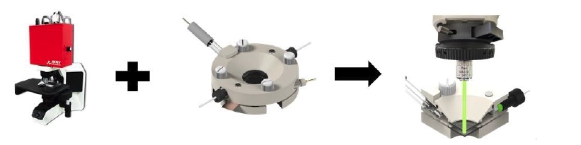
Combining Electrochemical and Raman spectroscopies can provide more detailed information about electrode reactions. We refer to this dual-function system as Combined EC-Raman. The Combined EC-Raman enables in-situ measurements with real-time monitoring and recording to track structural changes and identify adsorbed products or intermediates.
We have integrated the CHI electrochemical stage with our MRI micro-Raman spectroscopy. Depending on the electrolyte used, users can configure different laser wavelengths for Raman measurements, or automatically switch between 532 nm and 785 nm laser sources. After the experiment, Raman spectra from both wavelengths can be obtained for comparison.
The Combined EC-Raman system is designed to provide richer and more immediate information, making it a powerful tool for electrochemical researchers.(Patents: Taiwan I 750718, U.S. 11,340,114 B2)
-
STM TERS (Upgrade, Taiwan only)
This localized resonance region is commonly referred to as the “hot spot.” Within this region, the nanometer-scale precision of the STM enables the detection of Raman signal variations with spatial resolution down to several tens of nanometers.
-
Reference Specifications
– For a standard 532 nm setup:
►Range: 79~3500 cm-1, Resolution: 1.8 cm-1
►Range: 79~2100 cm-1, Resolution: 1.3 cm-1
► Example: The 85 cm-1 Raman signal of sulfur can be clearly detected.
– For 785 nm, the typical range is 150~3500 cm-1 with 1.8 cm-1 resolution.
– Other ranges depend on the selected laser wavelength.
Each system is supplied with silicon or sulfur reference samples for calibration.
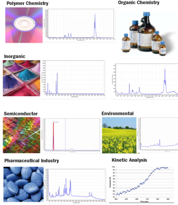
Applications